Got a fun exercise for you today: let’s use our electrical and schematic know-how to figure out how a circuit works in a schematic that leaves out a lot of useful labelling.
The circuit we’re interested in is the one labelled Door safety interlock.
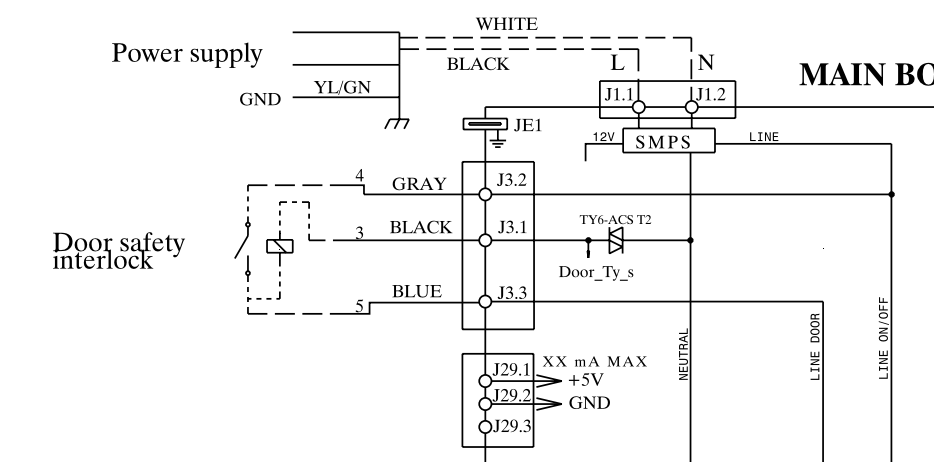
Based on its name and its context within the schematic — it gates Line to a number of loads elsewhere in the appliance — this circuit contains the door switch and the door lock. But how exactly does it work? We can assume that the switch is the door switch, but what is that rectangle with the slash through it?
We could sit around and guess, but that’s not why we’re here. We want to take a look at what we know about this circuit (and about circuits in general) and use that knowledge to suss out what’s what.
To that end, let’s start tracing our Line and Neutral and see what that tells us!
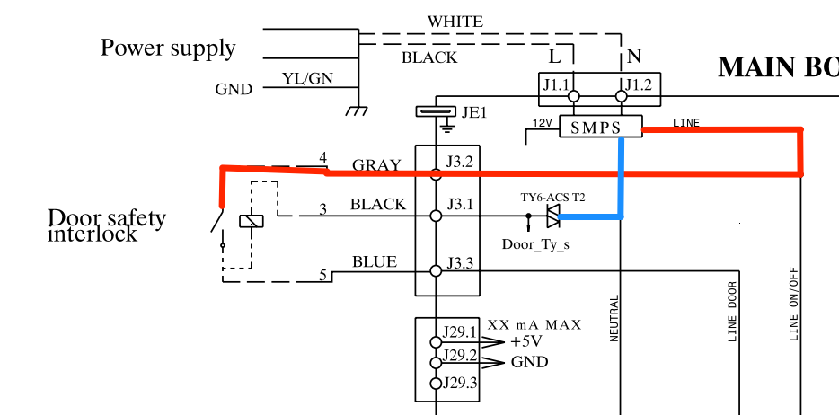
Here’s the state of the door safety interlock circuit with the door switch open (as drawn). We’re also looking at it with the triac open — that’s the symbol with the two triangles where the blue line ends, in case you’re not familiar with the schematic symbol for triacs (more about triacs in this post).
Right away, this should tell you something about that mysterious rectangle with a slash through it. Is that rectangle supposed to represent a switch or a load?
If you answered load, you’re correct! Think about it: if that rectangle weren’t a load, then when both the door switch and the triac are closed, you would have a dead short from Line to Neutral. Big sparks, no good. A circuit would never be designed to create a short in normal operation. So that rectangle must be a load. More specifically, the only thing it makes sense for that rectangle to be is a door lock solenoid.
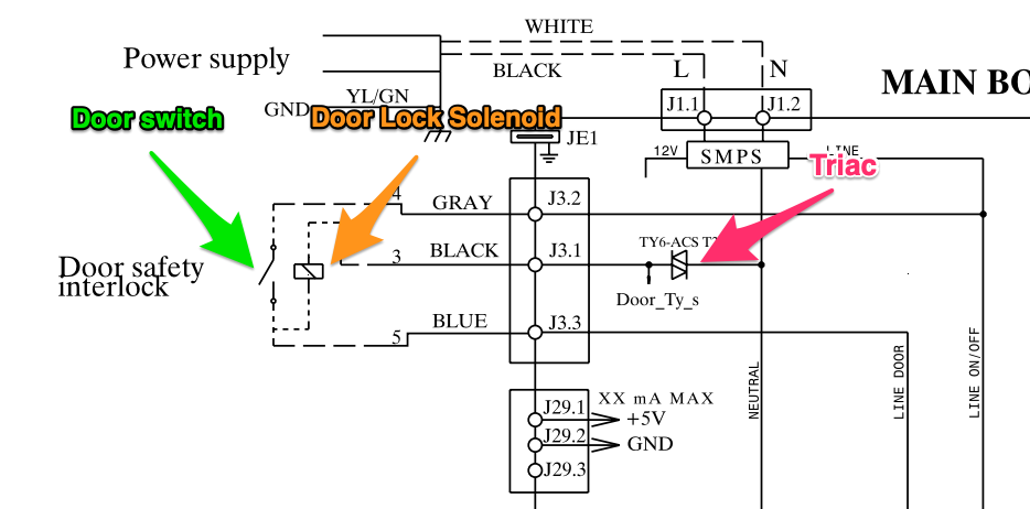
Why do we assume a door lock solenoid? Because we know that there must be a door lock present in this front-load washer. That’s a necessary component to keep the customer from opening the door during a cycle and dumping water all over their floor. And where else would the door lock be than in the door safety interlock circuit?
With this assumption, we can take a look at how the circuit must operate.
First, what happens when the customer closes the door?
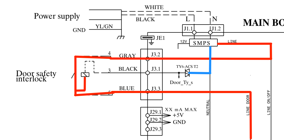
Now that door switch is closed, allowing line to reach loads elsewhere in the machine. But notice that the control board still has to close that triac to complete the power supply to the door lock solenoid. That makes sense, because the control would want to first sense that the door is closed, then actuate the door lock once a cycle as started.
Like so:
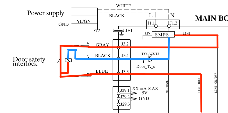
With both the door switch and the triac closed, we now have 120 VAC pushing electrons through that door lock solenoid. The electromagnetism of the solenoid will actuate a plunger (not shown on the schematic, probably since it’s a mechanical piece) which will hold the door shut. And once that plunger is in place, the control board will open that triac once more, cutting off Neutral to the solenoid. Just a short pulse of power is required to lock or unlock the door.
This is a classic case of using our functional understanding of circuits to work around a lack of information. By knowing how electricity, circuits, and loads must work, you can make logical deductions about circuits even when everything isn’t explicitly laid out for you.
Want to step up your circuit mojo to the next level? Click here to check out the Core Appliance Repair Training course right here at the Master Samurai Tech Academy.